Simple Rack And Pinion Steering Diagram

I Found This Helpful Answer From A Ford Mechanic On Justanswer Com Roof Truss Design Steel Trusses Roof Trusses

The Diagrams Here Show An Example Rack And Pinion System Left As Well As A Close Up Cutaway Of The Steering Rack Itself Electric Go Kart Go Kart Pedal Cars

Image Result For Solid Axle Suspension Diagram And Rack And Pinion Steering Rack Outdoor Chair Pads Tv Stand With Drawers

Rack Pinion Steering Gear Rack Small Trucks Repair

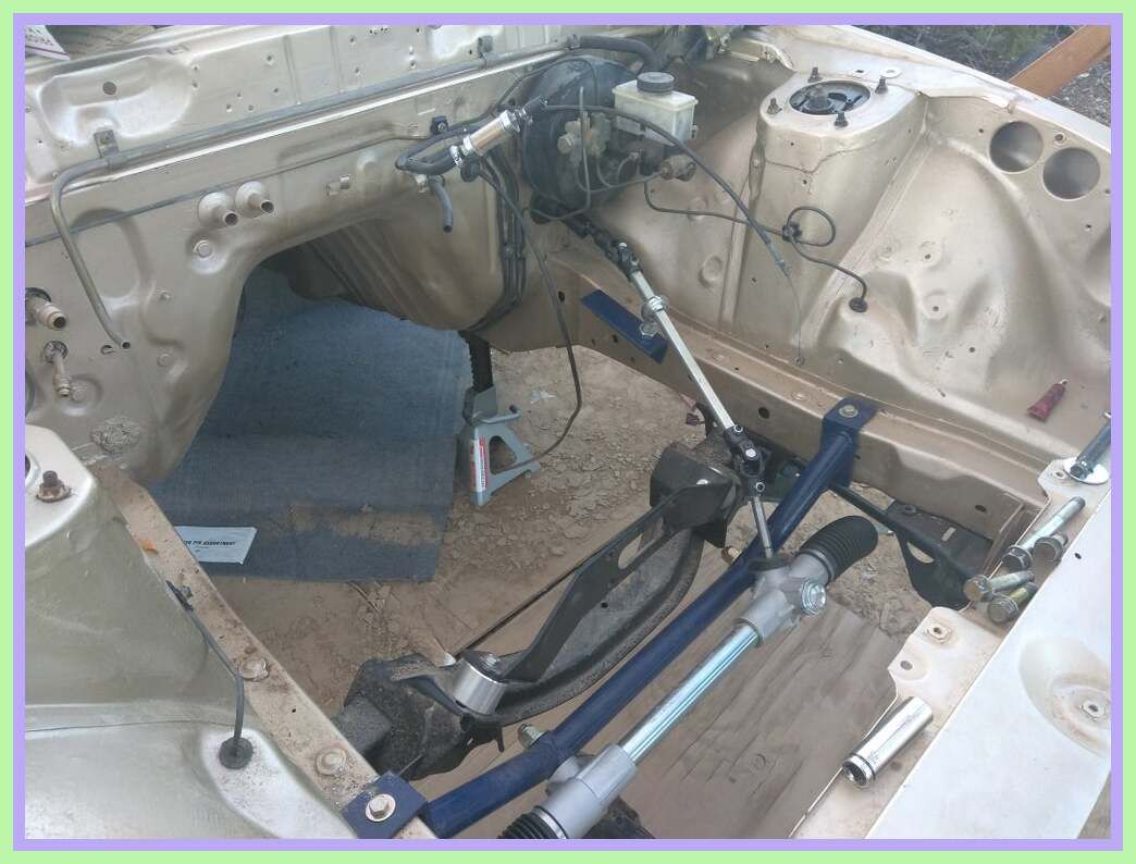
Steering Assembles Rack Pinion Steering Parallogram Streeing Car Mechanic Car Parts Automotive Mechanic

Rack And Pinion Parts Diagram Rack Diagram Parts
This pinion runs in mesh with a rack that is connected to the steering tie rods.
Simple rack and pinion steering diagram. Rack and pinion steering is quickly becoming the most common type of steering on cars small trucks and suvs. Working principle of rack and pinion steering gear. It is actually a pretty simple mechanism. A rack and pinion is commonly found in the steering mechanism of cars or other wheeled steered vehicles rack and pinion provides less mechanical advantage than other mechanisms such as recirculating ball but less backlash and greater feedback or steering feel the mechanism may be power assisted usually by hydraulic or electrical means.
A simplified rack and pinion steering diagram showing the column 2 rack and pinion 3 and tie rod 4 image via wikimedia commons laurensvanlieshout a tie rod links the rack to the kingpin. The use of a variable rack still using a normal. The rack and pinion steering box has a pinion connected to the steering column. Both the pinion and the rack teeth are helical gears.
Helical gearing gives smoother and quieter operation for the driver. The steering system converts the rotation of the steering wheel into a swivelling movement of the road wheels in such a way that the steering wheel rim turns a long way to move the road wheels a short way. A rod called a tie rod connects to each end of the rack. It also provides a gear reduction so turning the wheels is easier.

Rack Pinion Steering Automotive Mechanic Car Mechanic Automotive Technician

Stock Illustration Diagram Of A Rack And Pinion Rack Adjustable Table Gears

Rack And Pinion Diagram Front Wheel Drive Picture Of Rack And Pinion Steering Autos Prefieres

Rack And Pinion Diagram With Images Garden Tools Rack Technology

Rack And Pinion Steering Schematic Google Search Kart Auto

Image Result For Solid Axle Suspension Diagram And Rack And Pinion Steering Rod Diagram Axle

Rack And Pinion Steering 4runner Math Toyota 4runner

Rack And Pinion Steering Rack Control Valves Hydraulic Systems

Build Your Own Go Kart Front Wheel Steering Assembly Go Kart Steering Homemade Go Kart Go Kart

Automotive Steering System Infographic Diagram Showing Both Types In 2020 Automotive Mechanic Car Mechanic Automobile Engineering

82 Reference Of Rack And Pinion Car Repair In 2020 Wooden Doors Interior Kitchen Design Pictures Indoor Patio Furniture

Pin On Shed Barn Shed Base

99 Reference Of Rack And Pinion Car Repair In 2020 Repair Unicorn Bedding Unicorn Bed Sheets

Hydraulic Gear Pump Diagram Hydraulic Power Steering Is Very Dependable But Complex In Operation Hydraulic Hydraulic Steering Repair

Car Steering System Diagram Bing Images Automotive Mechanic Car Mechanic Automotive Engineering

Power Steering System Back And Pinion Rack And Pinion Steering Is The Most Common Type Of Steering On Cars Small Tr Small Trucks System Car Features

Engineering World Na Instagramie Electrical Power Steering System Engineeringregion Steeringwheel In 2020 Car Mechanic Automotive Mechanic Automotive Repair

Diagnosing Rack And Pinion Steering Problems Vibrations Tire Wear Computer Repair Computer Troubleshooting Computer Problems
Https Encrypted Tbn0 Gstatic Com Images Q Tbn 3aand9gcrcmm9vinmq1nt3ctvexz8wa6eibqsfr41evhdaowczpz8bffig Usqp Cau

What Is A Rack And Pinion Buy Auto Parts Rack Stuff To Buy Steering Wheel

Centre Point Steering Rack And Pinion Desert Kart Go Kart Steering Go Kart Homemade Go Kart

98 Reference Of Rack And Pinion Silverado 2005 In 2020 Farmhouse Sink Kitchen Rack Grohe Kitchen Faucet

Pin On Diy Furniture

Pin On Rack Book Amazon

Pin On Pigeon Red Map

Amazon Com Niome 110cc Go Kart 300mm Steering Wheel 320mm Assembly Full Steel Gear Rack Pinion Automotive Go Kart Gear Rack Steering Wheel

Power Steering Working Principle Animation Youtube

71 Reference Of Diy Rack And Pinion Table Saw Fence In 2020 Diy Table Saw Fence Diy Table Saw Table Saw Fence

Technic Steering Lego Lego Nxt Lego Projects

Lego Technic Building Tip Steering With No Gears Lego Technic Lego Gears Lego

Online Shop Hanging Margin Dual Disc Rear Axle Steering Wheel Before Conversion Kit Karting Accessories Atv Aliexpress Go Kart Buggy Go Kart Go Kart Steering

Pin On Front Door Paint Design Ideas

The Steering Gearbox Is A Unit That Can Be Found On Most Of The Larger Duty Trucks And Older Cars Gearboxes Are U Car Mechanic Automotive Mechanic My Mechanic

Pin On 110cc Steering Wheel

Click This Image To Show The Full Size Version Axle Farmhouse Sink Kitchen Rack

Pros Cons Cable Pully Steering Vs Rack Pinion Fiberglassics Forums Fiberglassics Com Diy Boat Boat Accessories Classic Wooden Boats

Suporte De Haste Ajustavel Para Volante Equipamento De Armazenamento 110cc 125cc 150cc Go Figurgo Cart 300mm Com Pinion Mon In 2020 Go Kart Cycle Car Electric Go Kart
43 Reference Of Rack And Pinion Steering For Drag Racing In 2020 Kitchen Window Treatments With Blinds Solid Oak Bedroom Furniture Shoe Rack Bench

Steering System 3d Model 3d Model System Model

Rack And Pinion With A Hydroboost By Streetrodding Com Rat Rods Truck Rat Rod Ford Trucks

Salem City Gravity Gran Prix Soap Box Derby Cars Derby Cars Soap Box Racer

Pin On Rack Closet Curtain

